
Technical review · About a 30-minute read
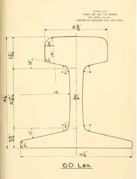
Pick up a section of 85-lb crane rail in almost any industrial yard in North America and you are holding a piece of Victorian engineering. The proportions of that rail — a head carrying 42 percent of the metal, a web carrying 21, a base carrying 37; a height exactly equal to the width of the base; fishing surfaces inclined at 13 degrees; a running surface crowned to a 12-inch radius — were fixed on August 2, 1893, when a committee of the American Society of Civil Engineers presented its Final Report of the Committee on Standard Rail Sections to the Society’s annual convention.5 The report was adopted, the mills cut rolls to the new drawings, and within seven years the section had captured most of American rail production. It was pushed off the main lines within two decades — and yet it never left the catalogs. The ASCE sections remain, today, the standard profiles for crane runways, mine track, transfer tables, and industrial spurs across the continent.
That is a remarkable service life for any engineering standard, and it makes the ASCE tee rail worth a close look: why the standard came about, what its designers were arguing over, what they decided and on what evidence, how the design fared under traffic, why its successors were drawn, and why — despite everything — it survives. The story is documented to an unusual depth, because the men who made it were prolific writers. The three ASCE committee reports survive in the Society’s Transactions; E. E. Russell Tratman, associate editor of Engineering News, compiled the whole subject into his Railway Track and Track Work (1897, with rewritten editions in 1901 and 1908), still the best single narrative of nineteenth-century American track practice1; and the metallurgical side played out in the pages of the Journal of the Iron and Steel Institute and the Transactions of the AIME. This review draws on those primary sources throughout; full citations are given in the endnotes.
Prologue: an American section
The tee rail itself is older than the standard by 62 years, and its origin story explains nearly everything about the form the ASCE committee inherited. In September 1830 the board of the Camden & Amboy Rail Road resolved to lay “all iron rail” rather than wooden stringers plated with strap iron, and sent its president and chief engineer, Robert L. Stevens, to England to buy it. On the voyage over, Stevens whittled model rail sections from wood begged off the ship’s carpenter. He knew John Birkinshaw’s rolled wrought-iron rail of 1820 — the ancestor of the British double-head — but Birkinshaw’s rail could not stand up on its own; it had to be gripped in a cast-iron chair at every support. Stevens saw that chairs were a luxury a thinly settled country could not afford, and added a flat rolled-on base wide enough for the rail to be spiked directly to its support. He designed the hook-headed spike to hold it and an “iron tongue” to join the ends — the direct ancestors of the modern track spike and joint bar.2
No English mill wanted the job of rolling so odd a shape until John Guest of the Dowlais works in Wales took it on, with Stevens personally guaranteeing the cost of mill breakdowns. The first rails, he wrote his father, “came from the rolls twisted and as crooked as snakes.” The first shipment — 550 bars, 18 feet long, 36 pounds to the yard — reached Philadelphia aboard the ship Charlemagne on May 16, 1831; a heavier rolling that followed weighed about 42 lb/yd and stood 3½ inches high.2 As the Camden & Amboy design settled, the rail carried a 2⅛-inch head on a base as wide as the rail was tall — and that proportion is worth pausing on, because base equal to height, the mark of the first American tee rails, is exactly what would be written into the American standard 62 years later. Stevens never patented the design; by the time he was advised to, it had become public property. When Charles Vignoles reintroduced the flat-bottom rail in England in 1836 it took his name there — Europe still calls the form the Vignoles rail — but the section is American by birth.1
The sixty years between Stevens and the standard can be compressed to three developments that set the ASCE committee’s agenda. First, the tee rail won its home market completely: by 1845 every American steam road was replacing strap rail and imported chair-borne rail with the Stevens pattern as fast as finances allowed, and the first domestic tee rails were rolled at the Montour Rolling Mill in Danville, Pennsylvania, that October.2 Britain went the other way, to the double-head and then (from 1858) the bull-head rail in cast-iron chairs weighing 26 to 56 pounds apiece — a system Tratman, with an American editor’s bluntness, judged to spend its money holding the rail up rather than carrying the traffic.1
Second, the material changed underneath the section. The wrought-iron rail of mid-century was rolled from a “pile” of bars welded together in the rolls — in W. H. Sellew’s phrase, “little more than a bundle of rods”4 — and as wheel loads grew, the welds let go: heads split and laminated under traffic. Because the poor iron needed a deep mass of metal to back the running surface, the mid-century American rail carried a bulbous, pear-shaped head against which no fish-plate could seat; joints had to be made in chairs, and the fished joint only became general practice around 1855, once flatter heads and higher webs gave the splice bars something to bear on.1 Steel ended the lamination problem outright. The first Bessemer steel rail — rolled from one of Robert Mushet’s crucible-cast ingots — went into the Midland Railway’s track at Derby station early in 1857, at a spot where iron rails died in three to six months; it came out in June 1873, some 1,250,000 trains — and as many detached engines and tenders — having passed over it.6 America’s first Bessemer rails were rolled at the North Chicago Rolling Mill on May 24, 1865, from ingots blown at the experimental Kelly-process works at Wyandotte, Michigan; the first commercial order followed from the Cambria Iron Works in August 1867.6 The famous head-to-head trials settled the economics: at Chalk Farm on the London & North Western, two steel rails laid on May 2, 1862 opposite the best iron were still in place in August 1865, worn evenly down about a quarter inch, while alongside them eight iron rails had been entirely worn out on both faces and the seventeenth face was in service.7 American roads reported the same in 1869 — steel outwearing thirteen, fifteen, seventeen sets of iron.4 All that remained was price, and price collapsed: from an average of about $166 a gross ton in 1867 to $28.50 by 1885 and $17.62 by 1898.6 Steel rail tonnage passed iron in 1877, and by 1883 the rolling of standard-section iron rails in America had, in James Swank’s words, virtually come to an end.6
Third — and this is the development that actually produced the ASCE standard — the section itself fell into anarchy. Steel invited redesign: the new metal did not need the pear head’s mass, and every chief engineer took the invitation personally.
The problem: three hundred patterns
By the early 1880s, designing one’s own rail section had become, in trackman W. M. Camp’s word, a fad. The numbers are startling. As late as 1881, by Sellew’s count, 119 patterns of steel rails of 27 different weights per yard were in regular manufacture, with 180 older patterns still in use — nearly 300 distinct sections on American railroads at once.4 Camp puts it at 188 patterns “considered standard” at the mills.3 Tratman diagnosed the cause without mercy:
“At that time there was an almost entire lack of uniformity in rail design, each engineer having his own ideas, and desiring to have his own special form of section on his own line. The rail mills therefore had to carry enormous stocks of rolls for all these sections, though many of the sections were practically identical, having minute variations as the result of the whim of the designer or his ignorance of the existence of a practically identical section.” — E. E. Russell Tratman, Railway Track and Track Work, 3rd ed. (1908)1
The cost of this vanity fell everywhere. Mills carried acres of idle rolls and could never roll for stock — every order was a special order, with the setup waste and the “wasters” (defective rails) that special orders imply. Railroads paid for it in price and delivery. And the sections themselves were frequently bad, because the same individualism that multiplied patterns also produced genuine design errors: heads flared outward at up to 10 degrees on the Lehigh Valley (one proposed section carried the flare to 20), heads with inward-sloping sides that Tratman flatly called “decidedly bad,” and — in a fashion that ran from about 1880 to 1888 — heads with top corners rounded to radii of ⅝ and ¾ inch to nestle the wheel fillet, which in practice let the wheel flange rub the side of the head and gouge it.1 Behind all of it stood a rising failure rate that nobody could confidently assign to section, steel, or mill practice.
This was, in short, exactly the situation a professional engineering society exists to fix. The fixing took twenty years and three committees.
Three committees, 1873–1893
The Society moved on rails three times, and each committee narrowed the question the next one would answer.
The first committee was appointed on January 8, 1873 — Ashbel Welch in the chair, with M. N. Forney, Octave Chanute, and I. M. St. John — and charged with nothing less than “the best form of standard rail sections of the United States,” along with the proportioning of rail weight to loads, methods of manufacture and test, the life of rails, and the causes of their breakage.4 Its 1874 report (Transactions, Vol. III) is chiefly remembered now for its careful iron-versus-steel service data, gathered at the exact moment the industry was deciding that question with its purchase orders. A standard section did not come of it; in 1873 the ground was still moving too fast.
The second committee attacked a prerequisite question: what shape should the top of a rail be, given the wheels that run on it? Created by a resolution at the Society’s Deer Park convention on June 25, 1885, the Committee on the Proper Relation to Each Other of the Sections of Railway Wheels and Rails — H. Stanley Goodwin, A. M. Wellington, Samuel Rea, George S. Morison, Thomas Rodd, S. M. Felton, Jr., and James Archbald — circularized some five hundred railway officers, received sixty-four detailed responses, and filed its final report on June 24, 1889.8 Its findings demolished a decade of fashionable wheel-fitting. The dread of sharp-cornered rails proved “greatly exaggerated”: round-cornered rails actually showed more side wear, because the rounded corner invited the wheel flange to ride against and cut the side of the head. Nor did rails principally die by abrasion — they were often destroyed “with little material abraded,” crushed once the flow of metal in the head reached its limit.1 The committee’s affirmative recommendations — a broad head relative to its depth, sides vertical, top crowned to a 12-inch radius, top corners of ¼-inch radius, lower head corners of 1/16 inch — became, almost verbatim, the head of the ASCE section.8
With the head settled in principle, the Society authorized a third committee to draw the sections themselves. It organized at the Society’s house on October 1, 1890, choosing G. Bouscaren — chief engineer of the Cincinnati Southern — as chairman and A. M. Wellington, author of The Economic Theory of Railway Location, as secretary. (Robert W. Hunt, the steel-works engineer who had supervised America’s first experimental steel rail rolling in 1865, later took over as secretary and signed the final report in that role.) The committee’s method is worth noting, because it explains the design’s character: each member was first asked to submit, independently, his own ideal set of sections. Ten sets came in, and Wellington’s tabulation showed nine of the ten already agreed on the 1889 head — 12-inch crown, sharp corners, vertical sides. The disagreements were quantitative: Wellington’s own submission, for instance, proportioned the metal 40 percent to the head, 22½ to the web, and 37½ to the base, against the 42/21/37 finally adopted.9 A final circular went to the chief engineer of every railroad with a hundred miles or more of track; fifty-five replied, and the most contested point in the whole correspondence was the radius of the top corner of the head.5
The final report — Paper No. 601, Transactions Vol. XXVIII — was presented on August 2, 1893, and adopted. It laid down thirteen sections, from 40 to 100 lb/yd in 5-lb steps, all geometrically of one family.5 One member dissented in part: George S. Morison held that the head, having been sized right for wear at 2½ inches on the 80-lb rail, should stay that width on every heavier section rather than growing with the rail, and filed minority plates for the 85, 90, and 95-lb weights to prove it.5 Morison lost the vote, but keep his argument in mind; the twentieth century largely took his side.
Anatomy of the standard: what they drew and why
The 1893 sections can be stated almost entirely in one sentence of constants. In every ASCE section the height equals the width of base; the metal is distributed 42 percent to the head, 21 to the web, and 37 to the base; the running surface is crowned to a 12-inch radius with top corners of 5/16-inch radius; the sides of the head are vertical, with 1/16-inch lower corners; the web faces are shallow concave arcs of 12-inch radius meeting head and base through ¼-inch fillets; the base corners are 1/16 inch; and the fishing surfaces — the underside of the head and the top of the base, where the joint bars clamp — are both inclined at 13 degrees.1 Every one of those numbers was an argument that had been settled, and the report explains most of the settlements.
Take them in order of importance. The 42/21/37 distribution was the committee’s core structural and metallurgical decision, and their reasoning was as much about the cooling bed as the track:
“To have a smooth track… it is of importance that the metal in the head and flange of the section should be as nearly balanced as economy will permit, thereby permitting the hot metal in the just-rolled rail to cool with the least internal strain… We decided upon 42% of metal for the head, 21% for the web and 37% for the flange.” — Final Report of the Committee on Standard Rail Sections, Trans. ASCE XXVIII (1893)5
A rail whose head vastly outweighs its base cools unevenly, bows on the hot bed, and locks in residual stress; the committee balanced head against flange to make a rail that could be rolled straight and stay straight. They reasoned about grain the same way: since “the wearing qualities of rails largely depend on the closeness of the grain of the steel in their heads,” they shaped heads that would still be receiving real work from the rolls as the metal cooled — a head finished cold is a head finished hard.5 And they deliberately stopped short of the wide, thin base that a pure moment-of-inertia calculation would suggest, because with a flange “both wide and thin,” the report warned, “difficulty will be experienced in making it fill out to the full designed width,” and flaws develop at its edges.5
The height-equal-to-base rule made every section stable against overturning in the same degree and gave the family its visual signature — the square envelope. Tratman states the design consensus of the period exactly: the width of base “should be equal to, but not greater than, the height of the rail.”1 The 13-degree fishing angles, identical top and bottom, defined a standard joint-bar seat across the whole family — a quiet decision with large consequences, since it meant a road’s joint hardware, drilling templates, and track tools no longer changed with every rail pattern. The 12-inch web radius put the web’s thinnest point at mid-height, thickening it toward both fillets where the stresses concentrate.
And the 5/16-inch top corner — the most fought-over 1/16 inch in American engineering — was a diplomatic instrument. The 1889 committee had recommended ¼ inch; the advocates of round corners, still numerous among the fifty-five responding chief engineers, wanted much more. The committee split the difference, as Tratman records, “partly to effect a compromise with the advocates of a round corner, and partly to make the section more generally applicable on curves,” the section being designed “particularly for the tangents and easy curves which compose by far the greater part of the railway system.”1
The thirteen sections were drawn to these rules and tabulated with their properties. The table below gives the leading dimensions of the ASCE family as rolled — including the lighter weights (below 40 lb) that the mills added after 1893 by extending the same proportions downward, which is why an 1893 standard today runs from 8-lb mine rail to the 100-lb section. Note the arithmetic elegance: pick any weight, and height, base, and the rest follow from the family rules.
| Weight (lb/yd) | Height = base (in) | Head width (in) | Web (in) | Area (in²) | I (in⁴) | Section modulus, head (in³) |
|---|---|---|---|---|---|---|
| 25* | 2¾ | 1½ | 19/64 | 2.39 | 2.50 | 1.77 |
| 30* | 3⅛ | 1-11/16 | 21/64 | 3.00 | 4.06 | 2.53 |
| 40 | 3½ | 1⅞ | 25/64 | 3.94 | 6.57 | 3.62 |
| 50 | 3⅞ | 2⅛ | 7/16 | 4.87 | 9.94 | 4.98 |
| 60 | 4¼ | 2⅜ | 31/64 | 5.93 | 14.56 | 6.62 |
| 70 | 4⅝ | 2-7/16 | 33/64 | 6.81 | 19.70 | 8.19 |
| 75 | 4-13/16 | 2-15/32 | 17/32 | 7.33 | 22.86 | 9.10 |
| 80 | 5 | 2½ | 35/64 | 7.86 | 26.38 | 10.07 |
| 85 | 5-3/16 | 2-9/16 | 9/16 | 8.33 | 30.07 | 11.08 |
| 90 | 5⅜ | 2⅝ | 9/16 | 8.83 | 34.39 | 12.19 |
| 100 | 5¾ | 2¾ | 9/16 | 9.84 | 43.97 | 14.55 |
* The 25 and 30-lb sections (like all ASCE weights below 40 lb) are post-1893 mill extensions of the family proportions; the 1893 report proper covered 40–100 lb in 5-lb steps. Dimensions per the Carnegie Pocket Companion (1921), cross-checked against current producer tables.
The committee’s design also paid the mills. Because the sections balanced head against base, they could be rolled at lower temperatures with less cambering; because they were standard, mills could roll to stock instead of to order; and the sharp corners, Tratman noted, had “no material effect upon the life of the rolls.” Fewer wasters, fewer seconds, fewer roll changes — the economics that had made 300 patterns ruinous now ran in reverse.1
Adoption: the standard takes the country
Standards proposed by learned societies do not always take. This one did, and quickly. Sellew records that within a few years about two-thirds of the output of the American rail mills conformed to the ASCE design.4 Tratman, wanting harder numbers, conducted his own survey in 1900: of fifty leading railways operating 120,000 miles of road, thirty-five — representing three-quarters of that mileage — had adopted the ASCE type as standard. His survey also answered the last lingering objection from the corner-radius wars: no excessive wheel wear had followed the sharp-cornered rails.1 When the Society checked again in 1906, the sections represented 65 to 99 percent of the output of the leading mills.11
The family also grew beyond its thirteen charter members at both ends. The mills extended the proportions downward to light rails — 8 through 35 lb/yd — for mines, industry, and contractors’ track, and these “ASCE” light sections (never in the 1893 report, but faithful to its rules) became and remain the standard American light-rail profiles. At the heavy end, sections of 105 to 120 lb were drawn on the same system as loads grew.1 A measure of the design’s reach: when the British Engineering Standards Committee drew its own flat-bottom sections in 1905, it adopted the ASCE signature wholesale — height equal to base, vertical head sides, 12-inch crown — differing chiefly in a 14-degree fishing angle.1
The loyal opposition: Dr. Dudley’s deeper rail
Not everyone signed on, and the most instructive holdout was the New York Central — because its dissent was not a chief engineer’s whim but the most data-rich rail research program in the country. Plimmon H. Dudley had joined the Central in 1880 and built for it the dynagraph car, a rolling instrument platform that traced the actual dynamic behavior of track under load; by the mid-1890s he had inspected some 25,000 miles of track with it, and he later devised the stremmatograph to record fiber stresses in the rail itself under moving trains — measurements, as Tratman noted, “beyond mathematical analysis” at the time.1 (A frequent error in later accounts puts Dudley on the ASCE committee; he served on none of the three, though his data appears in the 1893 report’s appendix and his was among the sixty-four responses of 1889.)8,5
Dudley’s measurements led him away from the square envelope. His sections — the first designed for the Central in 1883, revised repeatedly — were deeper than they were wide: his 80-lb rail stood 5½ inches on a 5-inch base, against the ASCE 80’s 5-by-5. He crowned the head to a 14-inch radius, rounded the corners at 5/16 inch by his own independent conclusion, carried a wider head (2-21/32 inches), and drew the web with generous fillets and its narrowest point above the center line — against the ASCE web’s mid-height minimum — to resist twisting, so that the head would not bend over the web nor the web over the base.1,5 His argument was the coming one: static wheel pressures on the contact patch already ran from 30,000 to 100,000 psi under passenger cars and 110,000 to 150,000 under locomotive drivers, and only broad heads on deep, stiff sections could take such loading without plastic flow.1 The Central never adopted the ASCE profile for its main tracks, and its results were hard to argue with: Dudley’s 100-lb high-carbon rails were carrying 250 million gross tons with a sixteenth of an inch of head wear.1 The ASCE section was a superb average; Dudley was designing for where the traffic was going.
Shortcomings: the section meets the twentieth century
The standard’s troubles came from two directions at once — the drawing office and the blast furnace — and it took the profession a decade of acrimony to apportion the blame.
The first problem was arithmetic. The committee of 1893 had designed for the locomotives of 1893; the report’s own instructions had capped the series at 100 lb because 80-lb rail was “then regarded as the heaviest likely to be extensively used” — only the Philadelphia & Reading had anything heavier in track, a few 90-lb rails.4 Then American motive power exploded. By 1906 the Society’s own follow-up committee reported that driving-wheel loads had increased 60 percent since 1893 while the maximum weight of rails in the standard had increased only 25.1 The section was being asked to do half again the work it was drawn for.
The second problem was buried in the proportions themselves. The ASCE base — wide as the rail is tall, and therefore thin at the edges, exactly the geometry the 1893 report had worried over — became a rolling-mill liability at heavy weights. Sellew, writing from inside the steel industry, is blunt: the thin bases “turned black in the rolls while the heads were still hot,” so the section came off the mill with its parts at different temperatures — residual stress in the finished rail — while the massive heads of the largest sections cooled so slowly that they were partially annealed, leaving the running surface soft and abradable. In the heavier weights then demanded, the ASCE design “was stated to be an impracticable one to roll.”4
Third, the steel under the section was itself in crisis. Rail failures climbed alarmingly after 1900 as Bessemer practice was driven for tonnage — big ingots, fast rolling, high finishing temperatures — and the arguments that had once been about corner radii became arguments about phosphorus, segregation, and finishing temperature. This debate had a long pedigree. Charles B. Dudley, the Pennsylvania Railroad’s pioneering chemist — the other great rail scientist named Dudley — had analyzed worn rails in landmark AIME papers of 1878 and 1881 and concluded that softer steel wore better; the steelmakers attacked the finding, the Pennsylvania specified to it anyway, and, as Sellew dryly records, “for several years following 1881 the rails were made too soft” before the pendulum swung back.10 The same fight ran through the Journal of the Iron and Steel Institute for thirty years — from Captain Bill Jones’s 1881 paper revealing American hard-driving practice to British makers, through G. J. Snelus on segregation in rail-steel ingots, to C. P. Sandberg’s pointed 1898 warning, “The Danger of Using Too Hard Steel Rails.”12 Out of the failure crisis came institutions rather than a single answer: C. B. Dudley led the founding of what became the American Society for Testing Materials (reorganized 1902, Dudley president until his death in 1909), whose specification for carbon-steel tee rails carries to this day the serial designation A1 — literally the society’s first standard.10
By 1905 the president of the American Railway Engineering & Maintenance of Way Association was telling his convention that “it is a positive fact that there is something wrong with the rail,” and that the Association could do no better work than to investigate it.13 The ASCE’s special committee of 1902 held the line for a while — reporting in 1905 in favor of no change to the standard — but by 1907 it had agreed to prepare modified heavier designs, and in 1910 it asked to be discharged, leaving rail sections to the railway associations.11 Its final report contains the era’s most level-headed verdict, quoting the AREA rail committee’s statistics: differences between sections could be “entirely annihilated by difference in chemical composition and by the treatment in furnace and mill.”11 The section mattered; the steel and the mill mattered more.
The successors — and what they changed
The American Railway Association moved first, presenting new sections on October 1, 1907 and issuing them as standards in 1909, in two series that split the old committee’s argument down the middle: Series A for the advocates of a thin head on a deep, stiff section (high moment of inertia), Series B for the advocates of a deep, narrow head with stiffness secondary.4 The ARA’s “cardinal principles” of 1907 read as a point-by-point audit of the 1893 drawing: metal in the base equal to or slightly greater than in the head; flange edges thick enough “to permit the entire section to be rolled at low temperatures”; web fillets as generous as possible; no fixed percentage distribution imposed across the series; and — the end of the square envelope — the width of base to be ⅛ inch less than the height.4 The Pennsylvania, characteristically, went its own way with the deep-headed P.S. sections of the same year, and the American Railway Engineering Association’s own profiles followed — 100, 110, and 120-lb sections in 1919, 130 and 140 in 1920, 150 in 1924 — each generation taller relative to its base, thicker in the web, heavier in the base edge. Morison’s 1893 minority position, and Dudley’s deep rail, had won the century: the modern AREMA 136RE stands 7-5/16 inches on a 6-inch base, its metal pushed out of the head and into depth.14
Two footnotes deserve recording. The new sections were no panacea — the AREA reported early results from the heavy-base ARA sections as frankly “disappointing,” with bad rail coming from the mills in the new profile as readily as in the old, “showing that the quality of the rail does not depend entirely upon the section”11 — the real cures were open-hearth (later controlled-cooled) steel and disciplined mill practice. And nothing in the successor programs touched the light end of the family at all: below 60 pounds there was nothing wrong with the ASCE proportions, and no one ever redrew them.
The long afterlife: ASCE rail today
Which brings the story to the present, because the 1893 standard never actually ended; it changed jobs. The conditions that exposed the section’s weaknesses — 60,000-lb axle loads, 70-mph tonnage, continuous welded rail — belong to main-line railroading. Industrial track kept nineteenth-century service conditions: moderate speeds, jointed rail, spike fastenings on timber ties. In that world the ASCE design’s virtues — the stable square envelope, the balanced section that rolls clean and straight, the standardized 13-degree fishing that a century of joint bars is made to fit — still govern, and its weaknesses never appear.
So the sections survived in production and in the catalogs, and the family has sorted itself by weight into the niches it serves today. The light end — 25 through 40-lb ASCE — is the rail of industrial material handling and overhead crane systems, with a share of hard-rock mining besides. The 60 through 85-lb weights carry tunneling and mining track and, again, cranes — the heavier runways and gantries. Above that the old standard finally gives way: 85 and 100-lb ASCE still see some industrial track service, but that territory now belongs mostly to the AREMA RE sections of 100 lb and upward. An engineer specifying a crane runway in 2026 still reaches for the same 85-lb section — 5-3/16 inches high on a 5-3/16-inch base, head 2-9/16 wide, web 9/16 — whose every radius was argued out in the correspondence of the Bouscaren committee. At Kimes Steel & Rail we stock, saw, drill, and fabricate these sections daily, working from dimensioned drawings of the 1893 profile (one of ours illustrates this article), and the splice bars, hook bolts, and compromise joints that go with them are all, in the end, hardware drawn to fit two 13-degree planes fixed in 1893.
The section’s reach still surprises us. As this article was being prepared, an engineering firm wrote to us for a quotation on 75-lb ASCE rail — for a gantry crane serving a commercial rocket launch complex. It is hard to improve on that as a measure of the standard’s endurance: an engineer tasked with moving hardware at the edge of the space age turns, without a second thought, to a profile fixed by committee in 1893. The men who spent their correspondence arguing over a sixteenth of an inch of corner radius could not have imagined the cargo; they would have recognized the drawing instantly.
It is worth stating plainly what that means: the ASCE tee rail is among the oldest engineering standards of any kind in continuous commercial production in the United States. It outlived the society committee that drew it, the locomotives it was drawn for, the Bessemer process that filled its first orders, and the main lines it was meant to carry. The men of 1893 set out to stop an epidemic of pointless variety, and they succeeded so thoroughly that their compromise — Wellington’s percentages rounded, the round-corner faction bought off with a sixteenth of an inch — became simply what light rail is.
Robert Stevens, whittling in a ship’s cabin in 1830, gave America a self-supporting rail whose settled form stood as tall as its base was wide. The eleven engineers of the Bouscaren committee, with sixty years of service data behind them, arrived at the same proportion by analysis. The century since has built taller for the heavy hauls — but on every crane runway and every mine gangway on the continent, the square-standing American section is still at work, carrying its 42 percent in the head.
Notes and sources
All nineteenth-century sources below are in the public domain and freely readable online at the links given. Where editions differ, page references are to the edition linked.
- E. E. Russell Tratman, Railway Track and Track Work, 3rd ed. (New York: Engineering News Publishing Co., 1908), esp. pp. 66–72 (rail history, ASCE committees and constants, Dudley sections, adoption survey), 80–82 (stremmatograph, rail life), 96–97 (joint history). archive.org/details/railwaytracktrac01trat. The 1st edition of 1897 is at archive.org/details/railwaytrackand06tratgoog.
- J. Elfreth Watkins, The Development of the American Rail and Track, as Illustrated by the Collection in the U.S. National Museum (Washington: GPO, 1891), pp. 658–674 — the fullest documented account of Birkinshaw, Stevens, the Dowlais rolling, the Charlemagne shipment, and early American adoption, drawn from Camden & Amboy records. archive.org/details/developmentofame00watk. (Watkins gives 18-ft first rails from C&A records; Tratman says 16 ft — we follow Watkins.)
- W. M. Camp, Notes on Track: Construction and Maintenance (Chicago, 1903), pp. 79–80. archive.org/details/notesontrackcons00camprich.
- William H. Sellew, Steel Rails: Their History, Properties, Strength and Manufacture (New York: D. Van Nostrand, 1913), pp. 1–17 (iron-rail life, first steel rails, section chaos, 1893 report context, ARA cardinal principles), 395–460 (manufacture). archive.org/details/steelrailstheirh00sell.
- “Final Report of the Committee on Standard Rail Sections,” Paper No. 601, Transactions of the American Society of Civil Engineers, Vol. XXVIII (1893), pp. 425 ff., presented August 2, 1893; with the Katte–Dudley correspondence in the appendix and Morison’s minority plates LXXVI–LXXIX. archive.org/details/transactionsofam28amer.
- James M. Swank, History of the Manufacture of Iron in All Ages, 2nd ed. (Philadelphia: American Iron and Steel Association, 1892), pp. 400–415 (Bessemer, Mushet, Wyandotte, North Chicago, Edgar Thomson), 440–441, 514–515, 537 (production and prices). archive.org/details/historyofmanufac00swanuoft. The 1867 ($166) and 1898 ($17.62) averages are the American Iron and Steel Association series; Swank prints the intermediate years and states the 1885 low of $28.50.
- “The Comparative Merits of Iron and Steel Rails,” London Quarterly Review, July 1866; reprinted in Henry M. Flint, The Railroads of the United States (1868). Transcription at cprr.org/Museum/Iron_and_Steel_Rails.html.
- “Final Report of the Committee on the Proper Relation to Each Other of the Sections of Railway Wheels and Rails,” Paper No. 425, Trans. ASCE, Vol. XXI (1889), pp. 223 ff. archive.org/details/transactionsofamciven21amer.
- “Progress Report of the Committee on Standard Rail Sections,” Paper No. 461, Trans. ASCE, Vol. XXIV (1891). archive.org/details/transactionsofamciven24amer.
- C. B. Dudley, “The Chemical Composition and Physical Properties of Steel Rails” and “Does the Wearing Power of Steel Rails Increase with the Hardness of the Steel?”, Trans. AIME, Vol. VII (1878); “Wearing Capacity of Steel Rails…”, Vol. IX (1881). Biography and bibliography in Memorial Volume Commemorative of the Life and Life-work of Charles Benjamin Dudley, Ph.D. (ASTM, 1911), archive.org/details/memorialvolumeco00ameruoft. The ASTM tee-rail specification’s A1 designation: astm.org/standards/a1.
- “Final Report of Special Committee on Rail Sections,” Paper No. 1177, Trans. ASCE, Vol. LXX (December 1910), including the 1906 adoption figures, the AREA Bulletin 116 quotation, and W. R. Webster’s call for 110–130-lb trial rollings. Full text at Project Gutenberg #18785.
- From the Journal of the Iron and Steel Institute: E. Williams, “The Manufacture of Rails,” Vol. I (1869), p. 156; W. R. Jones, “The Manufacture of Bessemer Steel and Steel Rails in the United States,” Vol. XVIII (1881), p. 129; G. J. Snelus, “The Distribution of Elements in Steel Ingots,” Vol. XIX (1881), p. 379, and “The Chemical Composition and Testing of Steel Rails,” Vol. XXI (1882), p. 582; F. W. Webb, “The Endurance of Steel Rails,” Vol. XXVIII (1886), p. 148; C. P. Sandberg, “The Danger of Using Too Hard Steel Rails,” Vol. LIV (1898), p. 76. General Index 1869–1900 at archive.org/details/journalironands02instgoog.
- President’s address, Proceedings of the Sixth Annual Convention, American Railway Engineering and Maintenance of Way Association (1905).
- Dimensional data for the ASCE family and modern AREMA sections: Carnegie Steel Co., Pocket Companion (1921), pp. 114, 172, archive.org/details/pocketcompanioni1921carn; cross-checked against current production data: Kimes Steel & Rail, “ASCE Rail Section Dimensions & Data,” kimessteel.com. One misprint found in a circulating distributor table — the 90-lb head depth — is corrected here from the Carnegie original.
Figures 1, 3, and 4 drawn for this article from the dimensions cited in note 14; interior proportions of the strap-rail and pear-rail profiles in Figure 1 are illustrative, as no standard existed. The dimensioned ASCE profile sheet (Figure 2) is a Kimes Steel & Rail engineering drawing.